________________________________________________________________________________
John Deere 130, 160, 165, 175, 180, 185 - Steering, Front Axle and Brakes
John Deere 130, 160, 165, 175, 180, 185 tractor Steering System
John Deere 130, 160, 165, 175, 180, 185
tractor - Remove steering wheel and shaft
Remove lock nut and washer. Drive out pin and remove steering
wheel. Remove pedestal shroud. Disconnect all wires and indicator lights
from dash. Loosen two nuts and remove two nuts. Lift dash. Remove cotter
pin and bearing. Remove cotter pin. Drive shaft up through pinion gear
and remove gear and washer. Remove bearing by aligning sector gear teeth
with outside diameter of bearing. Lift shaft and remove washers and
spring. Remove cotter pin and remove shaft. Remove steering gear support
- Disconnect drag link. Remove two nuts from support. Remove sector gear
support.
Disassemble and clean sector gear
Be careful when removing cotter pin.
Spring is compressed. Remove cotter pin, washers, spring, and support.
Mark sector gear and sector shaft for alignment for ease of assembly.
Remove bearing, washer and sector gear. Remove cotter pin to remove
steering sector support and bearing. Remove grease and clean parts in
solvent. Dry parts. Inspect and repair steering system - Inspect
steering shaft bushings for wear or cracks. Inspect springs for damage.
Inspect steering shaft and sector shaft for wear or bent conditions.
Inspect splines for wear. Inspect pinion gear and sector gear for worn,
broken or damaged teeth and wear on inside diameters. Inspect support
for cracks. Inspect sector shaft bearings for wear or cracks. Assemble
sector gear support (JD 130, 160, 165, 175, 180, 185) - Install bearing
and sector gear support on sector shaft. Install cotter pin, sector
gear, washer, and bearing on sector shaft. Make sure mark on gear aligns
with mark on shaft. Install sector gear support, washers, spring and
cotter pin on sector shaft.
Install steering gear support
Install steering gear support. Install
and tighten two nuts. Connect drag link. Install steering wheel and
shaft - Install shaft in pedestal. Install cotter pin, washers and
spring on steering shaft. Install bushing and cotter pin. Install
steering wheel. Drive pin through wheel and shaft. Install and tighten
washer and nut. Install steering shaft bushing. Put logo on steering
wheel in horizontal position and pull down on steering wheel. Install
washer and pinion gear, making sure dot on pinion gear is in alignment
with dot on sector gear. Install cotter pin. Connect drag link. Put dash
in position and install nuts. Tighten nuts. Connect all dash wires and
indicator lights. Install pedestal shroud. Adjust steering. Adjust
steering - Make sure dots on pinion gear and sector gear are aligned. If
wheels are straight forward no further adjustment is required, otherwise
continue with following steps. Disconnect drag link from spindle. With
dots still aligned, put wheels straight forward. Loosen nut and turn
ball joint until drag link fits easily into spindle without moving
wheels. Tighten nut against ball joint. Connect drag link to spindle.
John Deere 130, 160, 165, 175, 180, 185 tractor Front Axle
John Deere 130, 160, 165, 175, 180, 185
tractor - Remove front axle
Remove cap
screw, spacer, washer, and nut on both sides, and remove hood. Remove
muffler. Remove two cap screws and remove muffler guard. Remove electric
PTO clutch. Remove two cap screws from rear pivot anchor. Inspect and
repair front wheel and axle assemblies - Inspect wheel bearings for
wear. If wheel wobbles when rotated or bearings are visually worn,
replace bearings. Remove bearings from wheel by driving them out with a
punch. Put multi-purpose grease on new bearings. Drive new bearings into
wheel hub with driver. Inspect tie rod and drag link for bent condition.
Inspect ball joints for wear and free movement. Replace any worn or bent
parts. Put spindle in axle and check spindle bore for wear or being
out-of-round. Replace worn parts. Apply multi-purpose grease on spindles
before installing in axle. Grease wheel bearings and pack cavity between
bearings with multi-purpose grease and put a small amount on axle.
Install front axle
Install axle under JD 130, 160, 165, 175, 180, 185
tractor. Match boss on pivot anchors with holes in frame. Turn pivot
anchors against frame and align cap screw holes. Install and tighten two
cap screws. Install muffler guard with two cap screws. Install muffler.
Install hood with two cap screws, spacers, washers and nuts. If
necessary, adjust steering.
John Deere 130, 160, 165, 175, 180, 185 tractor Brakes and Linkages
John Deere 130, 160,
180 Brakes
A disk-type brake assembly is used on JD 130, 160, 180 Lawn
Tractors. The brake assembly is attached to the right-hand side of the
transaxle case. The brake disk is connected to the splined end of the
shifter and brake shaft on the transaxle. Depressing the brake pedal
pulls the brake linkage forward, which compresses two brake pucks on
each side of the disk. This stops movement of gears inside the transaxle
as well as tractor motion. To set the parking brake latch, both the
brake pedal and clutch pedal must be fully depressed. With both pedals
depressed, the parking brake lever can be lowered in the long vertical
slot on the deck. Lowering the parking brake lever positions the latch
around the brake pedal stud to lock both the clutch pedal and brake
pedal in the depressed (down) position. To release the parking brake,
both pedals must be fully depressed and the parking brake lever raised
and lowered in the short vertical slot on the deck. This design prevents
the operator from operating the tractor with the parking brake engaged.
John Deere 165, 175,
185 Brakes
A disk-type assembly is used on JD 165, 175, 185 Hydrostatic
Lawn Tractors. The brake assembly is attached to the left-hand side of
the differential case. The brake disk is connected to the brake shaft on
the differential. Depressing the brake pedal pulls the brake linkage
forward, which compresses the brake pucks on each side of the disk. This
stops movement of gears in the differential as well as tractor movement.
To set the parking brake, depress the brake pedal and lower the parking
brake lever in the vertical slot on the deck. The latch will lock the
brake pedal in the depressed position. To release the parking brake,
depress the brake pedal and raise parking brake lever out of long
vertical slot and lower it into short vertical slot.
John Deere 130, 160, 180 tractor - Remove
brake assembly
Put blocks under
tractor frame and remove right rear wheel. Disconnect brake linkage.
Brake assembly consists of loose parts. Do not lose parts when removing
assembly. Remove two cap screws and remove brake assembly. Slide disk
off shaft. Remove pad from behind disk. Inspect and repair brake
assembly (John Deere 130, 160, 180) - Inspect pads and plate for wear or
damage. Inspect disk for wear or cracks. Replace parts as necessary.
Install brake assembly (JD 130, 160, 180) - Brake pads and disk must be
free of grease and oil. Put LUBRIPLATE on brake shaft. Install pad and
disk with hub out. Install brake assembly. Install and tighten two cap
screws. Connect brake linkage. Install right rear wheel. Adjust brakes.
John Deere 165, 175, 185 tractor - Remove
brake assembly
To remove brake disk, transmission must be lowered. brake pads can be removed without lowering transmission. Put blocks under tractor frame and remove left rear wheels. Disconnect brake linkage. Remove two cap screws and remove brake assembly. Slide disk against frame and remove rear pad. Inspect and repair brake assembly (John Deere 165, 175, 185) - Inspect pads and plate for wear or damage. Inspect disk for wear or cracks. Replace parts as necessary. Install brake assembly (JD 165, 175, 185) - Put Lubriplate on brake shaft. Install pad and slide disk towards differential. Install brake assembly. Install and tighten two cap screws. Connect brake linkage. Install left rear wheel. Adjust brakes. Adjust brakes (165, 175, 185 models) - Make sure park brake is disengaged. With a feeler gauge, inspect clearance between pad and disk. Clearance should be 0.50 mm (0.020 in.). Turn nut to obtain proper clearance.
- JD 130, 160, 165, 175, 180, 185 Engine and PTO Clutch
- JD 130, 160, 165, 175, 180, 185 Transaxle service
- JD 165, 175, 185 Eaton Hydrostatic Transmission
- JD 165, 175, 185 Hydrostatic Differential
- JD 130, 160, 165, 175, 180, 185 Steering, Front Axle and Brakes
- JD 130, 160, 165, 175, 180, 185 Servicing Mower
________________________________________________________________________________
________________________________________________________________________________________
________________________________________________________________________________________
________________________________________________________________________________________
________________________________________________________________________________________
________________________________________________________________________________________
________________________________________________________________________________________
________________________________________________________________________________________
________________________________________________________________________________________
________________________________________________________________________________________
________________________________________________________________________________________
________________________________________________________________________________________
________________________________________________________________________________________
________________________________________________________________________________________
________________________________________________________________________________________
________________________________________________________________________________________
________________________________________________________________________________________
________________________________________________________________________________________
________________________________________________________________________________________
________________________________________________________________________________________
________________________________________________________________________________________
________________________________________________________________________________________
________________________________________________________________________________________
________________________________________________________________________________________
________________________________________________________________________________________
________________________________________________________________________________________
________________________________________________________________________________________
________________________________________________________________________________________
________________________________________________________________________________________
________________________________________________________________________________________
________________________________________________________________________________________
________________________________________________________________________________________
________________________________________________________________________________________
________________________________________________________________________________________
________________________________________________________________________________________
________________________________________________________________________________________
________________________________________________________________________________________
________________________________________________________________________________________
________________________________________________________________________________________
________________________________________________________________________________________
________________________________________________________________________________________
________________________________________________________________________________________
________________________________________________________________________________________
________________________________________________________________________________________
________________________________________________________________________________________

 JD SPECS
 JD LOADERS
 JD MAINTENANCE
 JD INSTRUCTIONS
 JD PROBLEMS
 JD 2025R
 JD 3039R
 JD 4044R
 JD 4105
 JD 4720
 420 Loader
 419 Loader
 510 Loader
 512 Loader
 520 Loader
 520M Loader
 540M NSL
 540 Loader
 440R Loader
 H180 Loader
 JD 5045E
 JD 5085E
 JD 5100M
 JD 6105R
 JD 6120M
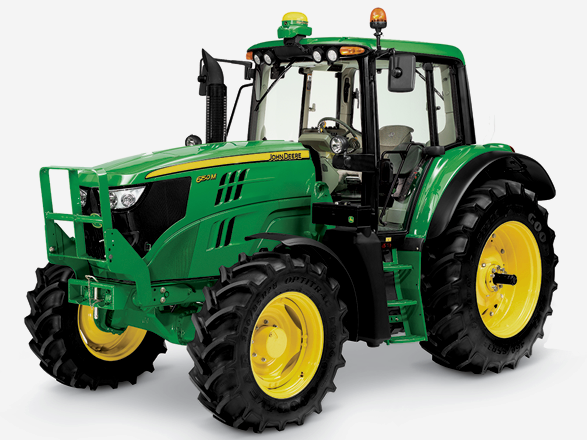 JD 6155M
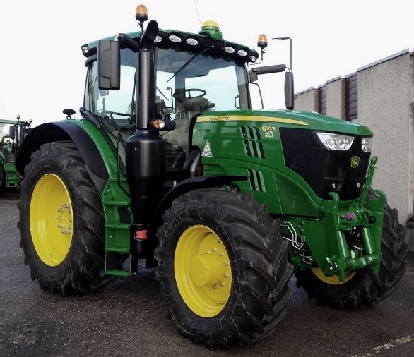 JD 6195R
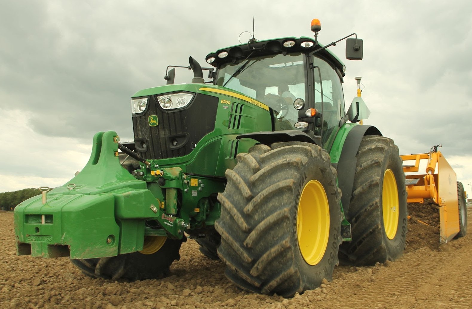 JD 6210R
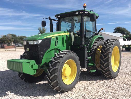 JD 7210R
 JD 7250R
 JD 7310R
 JD 8245R
 JD 8295R
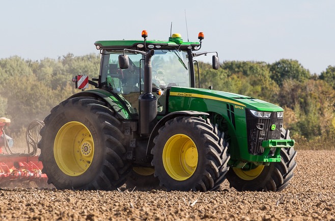 JD 8370R
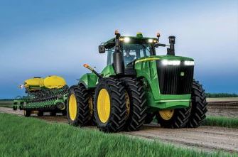 JD 9370R
 120R Loader
 D120 Loader
 H120 Loader
 45 Loader
 200CX Loader
 D160 Loader
 D170 Loader
 H160 Loader
 H165 Loader
 H240 Loader
 210 Loader
 220R Loader
 300E Loader
 300X Loader
 300CX Loader
 JD 9420R
 JD 9510R
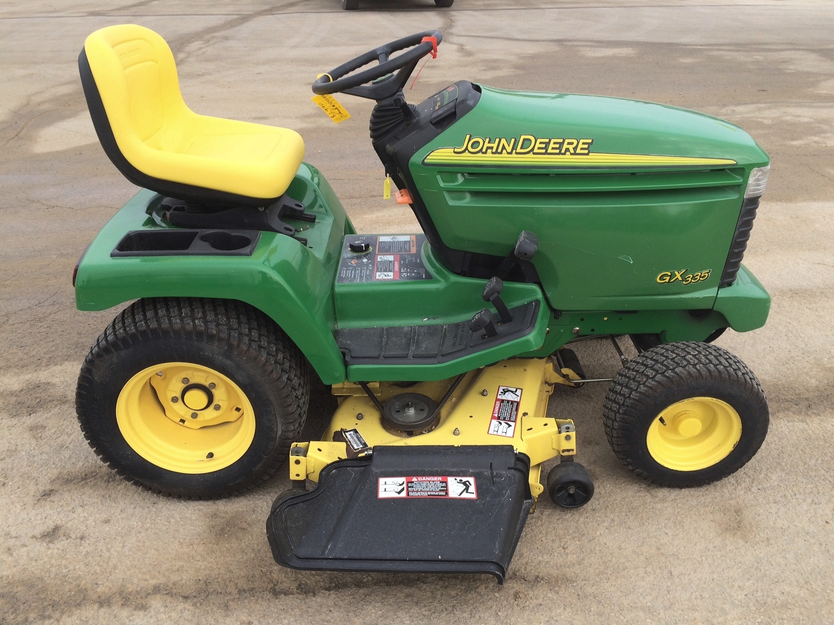 JD GX335
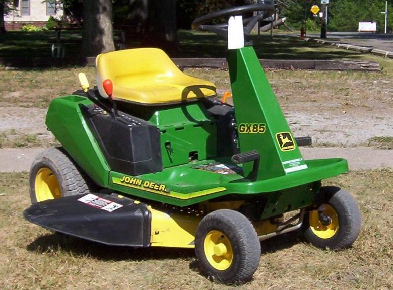 JD GX85
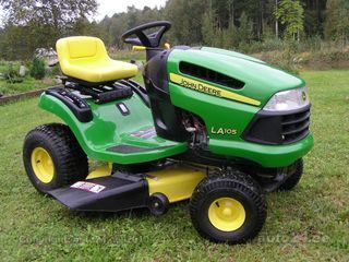 JD LA105
 JD 5065M
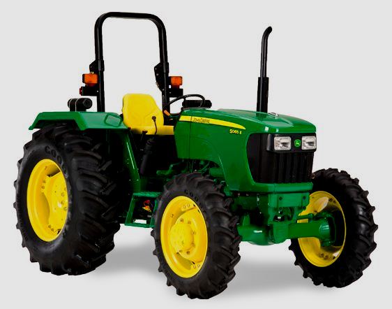 JD 5055D
 JD 5115R
 JD 5105M
 JD 6110R
 JD 6130D
 JD 6225
 JD 7530
 JD 4044M
 JD 7185J
 300 Loader
 300R Loader
 320R Loader
 400E Loader
 410 Loader
 430 Loader
 460 Loader
 521 Loader
 531 Loader
 541 Loader
 551 Loader
 631 Loader
 651 Loader
 661 Loader
 603R Loader
 JD D130
 JD D160
 JD 325
 JD 335
 JD 345
 JD 2520
 JD 3005
 JD 3720
 JD 1025R
 JD 3033R
 JD 5090EL
 JD 5100MH
 JD 5075GV
 JD 6090RC
 JD 6110B
 623R Loader
 643R Loader
 731 Loader
 746 Loader
 751 Loader
 533 Loader
 583 Loader
 633 Loader
 653 Loader
 683 Loader
 H260 Loader
 663R Loader
 663 Loader
 683R Loader
 753 Loader
 JD 6125J
 JD 6150RH
 JD 6210J
 JD 7195J
 JD 8310
 JD 6325
 JD 5525
 JD 5083EN
 JD 5100GN
 JD 5125R
 210C Backhoe
 300D Backhoe
 310G Backhoe
 410G Backhoe
 710G Backhoe
 80 Loader
 100 Loader
 146 Loader
 148 Loader
 158 Loader
 168 Loader
 175 Loader
 522 Loader
 542 Loader
 540R Loader
 562 Loader
 563 Loader
 673 Loader
 741 Loader
 L108 Automatic
 L120 Automatic
 LA110 Automatic
 LA120 Automatic
 LA150 Automatic
 LT155
LT155 LT160 Automatic
 LT180 Automatic
 LTR180
 X165
X165 E100
E100 E120
E120 E150
E150 LTR166
 LA135
LA135 LA165
LA165 LX277
LX277 LX288
LX288 LX255
LX255 S240
S240 GT235
GT235 G110 Automatic
 JD 3203
 JD 5520
 JD 316
 JD 420
 JD 425
 JD 445
 JD_5050D
 X300
X300 X304
X304 X310
X310 X110 Automatic
 H310 Loader
 H340 Loader
 H360 Loader
 H380 Loader
 H480 Loader
 240 Loader
 245 Loader
 260 Loader
 265 Loader
 600R Loader
 620R Loader
 640R Loader
 660R Loader
 680R Loader
 JD_5039D
 X146R
X146R X360
X360 X155R
X155R X140 Automatic
 X350
X350 X380
X380 X500
X500 X590
X590 X700
X700 3036E
3036E 2038R
2038R 3038R
3038R 4049M
4049M JD 4100
 X738
X738 X740
X740 X748
X748 X749
X749 X950R
X950R JD 4510
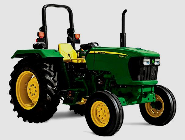 5045D
5045D 5050E
5050E 5060E
5060E 5078E
5078E